
1 of 12
Contact the Seller
2019 . PONTON122m
Request price
In verkoophaven, China
| Year | 2019 |
| Make | . |
| Model | PONTON |
| Class | Cruise Ship |
| Length | 122m |
| Fuel Type | Other |
| Hull Material | Steel |
| Hull Shape | Other |
| Offered By | Kriesels Shipbroker BV |
2019 . PONTON
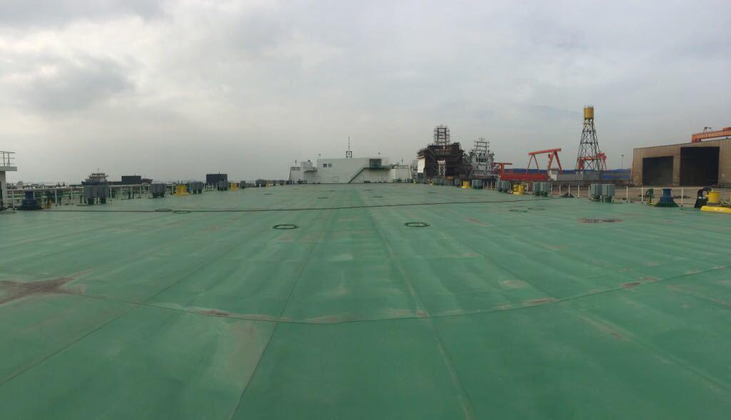
The vessel will be a non-propelled flat top barge suitable for carriage of ROVs, heavy equipments and structures on deck, and also fresh water.
HULL SPECIFICATION
GENERAL DESCRIPTION
The vessel will be a non-propelled flat top barge suitable for carriage of ROVs, heavy equipments and structures on deck, and also fresh water / sea water in tanks.
The barge will have spoon bow and raked stern and raised deck forward.
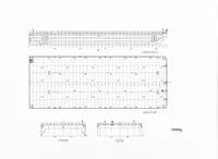
The vessel is sub-divided by means of three longitudinal and six transverse bulkheads including the collision bulkhead. All these compartments will be water ballast Tanks except the forward void tanks.
The vessel will have a double-chine hull form and twin stability-skegs aft.
Any components, appurtenances, interfacing equipment or accessories, not stated in this specification or drawings but deemed required for normal operation of the vessel as per class requirement or good marine practice, shall be provided by the builder at its own cost.
PRINCIPAL PARTICULARS
Length Overall: 400 FT (121.9M)
Breadth Mld.: 120 FT (36.6M)
Depth Mld.: 25 FT (7.6M)
Maximum Submersion: 1 M below deck (i.e Maximum Draught of 6.6M)
Dead Weight: Abt. 20,000 Tonnes at 6.0 M draft.
Capacities
Water ballast: Abt. 18,500m3
Fuel oil: Abt. 700m3
Fresh water: Abt. 5m3
Uniform deck load: 30T / m2
Deck Area: 4050 m2
CLASSIFICATION
The vessel will be built under special survey of ABS to obtain the Classification “+A1 Tank Barge” with descriptive note “Deck Cargo” and “Water Carrier” in accordance to rules and requirements in force at the time of signing the Contract.
The builder will pay all Classification, survey fees incurred during building.
Registration shall be to Owner's accounts.
CERTIFICATES
The following certificates will be supplied to the Owner at the time of the delivery of vessel:
1) Builder's Certificate
2) Classification Certificate (Hull)
3) Safety Construction Certificate
4) Loadline
5) Tank Slosing Calculation Statement or Certificate issued by ABS
The cost incurred for surveys, classification and issue of certificates will be borne by the Builder.
APPROVAL OF DRAWINGS
All plans will be submitted to the Owner for approval in triplicate before work is commenced. Owner to approve within 21 days upon receipt of drawings.
The Builder will at the same time submit to the Classification Society copies of all necessary plans for their approval.
Manufacturer's booklet, drawings and information for servicing machinery will be provided by the shipyard, as relevant and if available from manufacturer.
WORKMANSHIP AND MATERIALS
All materials and workmanship, machinery and outfitting etc., will be for marine use and of good quality. All steel plates, sections to be to Classification requirements and approval.
INSPECTION OF WORK IN PROGRESS
The Owner and his representatives will have the right of access to the shipyard, at all reasonable times during construction, for the inspection of the vessel, materials, workmanship and machinery, in accordance with the approved plans.
STABILITY BOOKLET
A simple stability booklet (for deck cargo barge criteria) will be prepared, based on lightship as estimated and to include hydrostatic particulars, cross curves, etc. Condition for maximum draft will be included along with two intermediate ballasted conditions.
GLM loadmaster is to be provided for shore use.
Final stability booklet is to be submitted to class after launching, including lightship, 25%, 50%, 75% and fully ballasted with balance deadweight capacity for deck cargo.
WELDING
Vessel will be of all welded steel construction, in accordance with Classification requirements.
Where possible, the structure will be prefabricated in assemblies and subassemblies, to give the maximum possible amount of down hand welding.
FRAMING
The side shell, bottom and deck will be longitudinally framed supported by transverse web frames and transverse watertight bulkheads, except bottom forward which may be transversely framed.
The space of the longitudinal will be about 750mm max.
MAINDECK AND PERMISSIBLE DECK LOADING AND CALCULATIONS
The maindeck will have no camber and no sheer.
The deck will be designed and constructed to withstand uniformly distributed deck cargo loadings of 30 Metric Tonnes/Sq. Metre. Point loadings on deck, in all typical locations are to be calculated and stated on General Arrangement with value and formula.
Void space / cofferdams to be provided above fuel oil tanks.
All openings in the deck plating will be well-radiused, carefully cut and finished to avoid notching.
Longitudinal and transverse strength calculations are to be submitted and approved by class.
Sloshing test is to be done and certificate issued by class.
Strength calculations of Towing bracket, fair lead, and bollard are to be done by designer and indicated on the relevant drawings.
PIPE TUNNEL
Pipe tunnel to be provided one (1) each port & starboard side underdeck within the ballast tanks up to the pump room for the water ballast pipes and air vents.
SKEGS
Two (2) Stability skegs of double plated type will be fitted at aft end.
WATERTIGHT MANHOLES
Each Tank compartment will have two (2) watertight manholes. Manholes for the side Tanks will be located in the outboard bulkheads. Access to the centre tanks is through the W.T. Manhole fitted on the portside & starboard longitudinal bulkhead.
All manholes to be flush type.
SEA CHESTS
Two (2) low seachests are to be provided in pump-room.
FENDER & HANDRAILS
At Port and Stbd. sides of Bow split pipe half round fender of 250mm dia., constructed from Schedule 40 pipe will be fitted.
Heavy duty tyre fenders each of 1500 x 500 are to be fitted port & starboard side all around with 22mm stainless steel chain from pad eyes 25mm thick fitted on deck sides with details to be owner approval.
Portable handrails are to be fitted on deck side with details to be owner approved.
PREPARATION OF STEEL FOR PAINTING
The steel work will be pre-blasted to SA 2.5 to remove all mile scale, rust and any foreign matters.
During construction, any defects in primed surfaces will be made good before applying finishing coats.
PAINTING
Paint Schedule to be generally as follows based on "Jotun" make for builder's guidance only. Final paint supplier and painting scheme to be mutual agreed. UWILD to apply to save intermediate dock requirement. The coatings in the FW/SW ballast tanks shall permit the tanks to carry either fresh water or sea water.
a) External surfaces with one (l) coat of primer F/C MUKL Z NO.2001 FW with DFT 30 mic in shop after blasting.
b) Main Deck Area
One (1) coat Jotaguard 85 brown 150 mic
One (1) coat Jotaguard 85 black 125 mic
c) Topside (Waterline to deck level)
One (1) coat Jotaguard 85 brown 125 mic
One (1) coat Jotaguard 85 black 125 mic
e) Bottom (Flats to waterline)
One (1) coat Jotaguard 85 black 125 mic
One (1) coat Jotaguard 85 brown 125 mic
One (1) A/F Sean Forec 30 150 mic
f) Water Ballast Tanks, Void Tanks, Pump Room & Tunnels
One (1) coat Jotaguard 85 brown 125 mic
One (1) coat Jotaguard 80 black (Strip boat) 125 mic
One (1) coat Jotaguard 80 black 125 mic
g) The Other Areas
The other areas not covered in the above are to be recommended by paint supplier for owner approval.
LADDERS
Ladders will be fitted under access manholes to void spaces where required. Two sections of “Pigeon Hole” recessed ladder on hull external on both port and starboard side forward and aft. Each side two sections of ladder.
VESSEL’S NAME
The vessel's name will be placed on both sides forward & aft. Both the vessel's name and port of registry will be placed at stern.
All letters will be outlined by a 6mm thick plate continuously welded to shell.
DRAFT NUMERALS
Draft marks in metric system shall be placed on both sides of bow, midships and stem being outlines by a 6mm thick plate welded to shell and painted in contrasting colour.
Loadline markings will be similarly dealt with.
Push patch markings to be provided on the shell plate in way of transverse bulkheads.
OUTFIT SPECIFICATION
ANCHOR WINDLASS & RECOVERY WINCH
One (l) set of electro hydraulic operated Anchor Windlass with gypsy suitable for 50mm Grade 3 chain at 12 m/ min and one (1) electro hydraulic recovery winch drum will be provided on main deck. Recovery winch drum 10 tonnes pull at 0-15m/min drum capacity 200 x 30 dia wire rope. Oil tray to be provided around hydraulic equipment base/foundation. One hydraulic power pack should be provided for the ANCHOR WINDLASS & RECOVERY WINCH and four (4) CAPSTANS.
ANCHOR, WIRE AND CHAIN CABLES
One (1) baldt anchor of 4000 KG weight will be provided.
The anchor will be complete with 247.5m length chain cable of 50mm dia Grade 3.
Four (4) Nos. white polypropylene mooring ropes each 170m length, 8 inch circumference and both end spliced. stored in pump room .
CAPSTANS
Four (4) nos. electro hydraulic operated capstans to be provided on main deck forward and aft (P&S) pull 10 tonne at 12m/min. Light Hauling in speed 30m/min. Remote control to be arranged.
DECK FITTINGS
Following deck fittings will be provided:
1) Six (6) nos. of 500mm dia fabricated double bollard complete with foundation, fitted on each side Port & starbard. Each single bollard to be of 50t SWL load capacity. Four (4) nos. of 500 mm dia crossbit of SWL 55 tonnes are to be provided. Special attention to be paid to the under deck stiffening.
2) Ten (10) nos. of panama chocks each of 50t SWL.
TOWING ARRANGEMENT
Towing Bridle
One forerunner studlink chain cable of 20m long x 72mm diameter, grade U3.
Two bridle studlink chain cables grade U3 of 27.5m long x 72mm diameter, end link at both sides, grades U3
Three Kenterlink shackles, SWL 200mT
One delta or fish plate SWL 200mT
One retrieving wire of 50m long x 38mm, galvanised, closed speller socket on one end with 17mT SWL shackle
Two Master Link SWL each 200 Tonne
Two Kenterlink Schackles SWL 200 Tonne
Emergency Towing
One bridle stud link chain cable of 10m long x 72mm diameter, grade U3,
One steel wire of 110 m long x 72mm diameter, galvanised.
One white and floating polypropylene of 50m long x 2” diameter.
One orange floating buoy (Norwegian) 1m diameter, connected to free and a 25mm dia polypropylene line.
Clips to be provided for stowing the emergency tow wire.
One Crosby Schackle SWL 55 Tonne
One Crosby Schackle SWL 25 Tonne
One Master Ling SWL 200 Tonne
One Kenterlink Shackles SWL 200 Tonne
2 smit bracket each of 400T SWL and 2 towing fairlead each of 200T SWL for main tow line and 1 x 400 T SWL smit bracket and towing fairlead 200t SWL for emergency tow line to be provided.
FRAME
A fixed A - frame davit to be provided at bow for retrieving the towing bridle etc with rigging to the recovery winch.
NAVIGATION LIGHTS
One set (1) of SOLAR operated navigation lights (constant for 5 NM) complying with COLREG requirements:
- One (1) green side light
- One (1) red side light
- One (1) white stern light
- One (1) white anchor lights
- One (1) removable signal mast on aft deck
LIFE SAVING EQUIPMENT
Life buoys, fitted with smoke signal and self-igniting light (4 off). Life vests (8 off)
FIRE FIGHTING EQUIPMENT
Spread at various locations (i.e. control room, pump room, generator room) consisting of portable powder fire extinguishers and portable CO2 fire extinguisher.
ANODES
For cathodic protection, Aluminium/Zinc anodes will be fitted. Suitable for 3 years protection. Both internal and external protection is required.
MACHINERY SPECIFICATION
GENERAL
All material and equipment shall be provided with ASBESTOS – free certificates.
The design of machinery and pipework system is to enable the following:
1) Ballast or deballast the barge via 500A piping within 5 hours by 2 pumps each of 2000m3/H, 12m head.
2) Transfer ballast water between tanks on the same or to the other side port & starboard
3) Receive or deliver fresh water via 200A piping by client provided portable pumps when required
4) Operate anchor windlass, tow bridle recovery winch and capstans electric hydraulically.
GENERATORS
Two (2) sets, 370 kW, 400V, 3-phase, 0.8PF, 50Hz, 3-wire, diesel engine driven housed in on main deck forward capable of parallel operation. Electrical power system shall be provided with international shore connection. The prime mover is air cooled, the cooling fresh water compensation tanks are to be topped up from the 5m3 fresh water tank fitted below the raised deck. A fresh water line is also to be extended to a washing sink on main deck for cleaning purpose. A daily tank is to be fitted below the raised deck to receive fuel from fuel tank, with high and low level alarm. The high level alarm is to activate auto cut off of fuel supply via fuel transfer pump, while the low level alarm is to activate supply of fuel.
Generator air cooling blower side is to be approx. 900mm off the house window in order for the hot air to dissipate outside directly. And this water tight windows are to be closed when engine is stopped.
SW / FW PUMPS
Four (4) Nos. each 2000m3/hr x 12m.
Each pump is driven by an electric motor (400V/3Ph/50Hz). Soft starting arrangements to be provided to limit starting current to 1.2 times normal operating current.
SW/FW pumps are interconnected with bypass piping and valves such that if one (1) pump is not operating, the other pump can be used. One (1) compressor of 30bar, 20m2/H, with suitable air reservoirs to be provided by builder to serve self priming of SW/FW pump.
REMOTE CONTROL SYSTEM
Remote control system with two (2) control panels incorporating touch monitors for SW/FW system auto operated valve actuators are to be remotely located at the forward control room on raised deck together with starters for the SW/FW pumps & air compressor. Alarms of High High level (HH), High level (H), Low level (L), and Low Low level (LL) are to be set by operator for the system linked with action of valves via remote control.
TANK LEVEL GAUGING SYSTEM
Tank level gauging system is to be provided with One (1) set of sensor each for twenty (20) SW/FW tanks. System to be suitable for sea water & fresh water application.
Additional level gauging system is to be provided for remote draft readings one (1) each at forward and aft port & starboard side. Suitable outboard openings on hull and piping for sensor fitting are to be arranged with class approval.
For each of the 20 FW/SW tanks and fuel tank, one (1) sight glass (liquid level meter) is to be fitted locally, for level reading in the event of sensor faulty and sounding impossible from main deck due to cargo stowage.
STRIPPING / BILGE PUMP
One (1) horizontal self priming centrifugal pump 50m3/hr x 15m head.
AUTO OPERATED VALVES & MANUAL VALVES
All valves in the SW/FW piping system, lines are electrically actuated and can be operated via the control panel. All controls to be local and remote in control room. Each of the Twenty (20) SW/FW tanks are to be fitted with:
- filling pipe with remote controlled on/off valve (20 in tanks plus 11 in pump room)
- suction pipe with remote controlled flow adjustable valves (20 in tanks plus 5 in pump room)
For remote draft reading at forward & aft port & starboard side, suitable valves are to be fitted with class approval.
At place of each level gauging sensor, manual isolation valves are to be fitted for sensor maintenance or replacement.
BATTERIES
2 x 24 Volt / 200 AH (maintenance free), with solar light charging system.
FUEL OIL TRANSFER PUMPS
One (1) Nos. each 50 m3 / hr at 15m head. Each pump is driven by electric motor (400V/3ph/50Hz) manifold, piping and values to be provided for taking bunkers and also for supplying fuel to the Tug to enhance the range. Auto cut in/cut off system are to be provided in the starter to start/stop fuel supply automatically from fuel tank to daily tank in the generator house once low/high level alarm is activated.
VENTILATION SYSTEM
Air circulation to the generator house shall be via an axial flow fan with mushroom head, capable of supplying sufficient air and installed on the raised deck. Exhaust air from generators shall be via motorized louvers.
Prime movers of generators are air cooled, adequate heat radiation exits are to be provided to ensure safety and efficiency of power generation.
Prime mover exhaust pipework are to be fitted with seawater separator tank and drain pipe to prevent seawater going into the engine.
Pump room ventilation shall be via an axial flow fan with mushroom head, capable of supplying 44,000 m3/h and natural exhaust shall be via louvre provided with weather tight closing arrangement located on raised deck.
BALLAST WATER TREATMENT PLANT
No ballast water treatment plant is provided.
AIR PIPES FOR SW/FW TANKS
Common air pipe to each SW/FW tank will be led to above deck routed through the pipe tunnels (P + S). and the vent headers should be arranged on the fore deck.
SW/FW PIPING FOR SW/FW TANKS
The pipes should be of FRP or PE pipe and to be approved by owner and builder and class.
SOUNDING SYSTEM
All tanks to be provided with manual sounding system using sounding pipes, flush with deck as a back up for tank ganging system.
Show More
Dimensions
| Length Overall | 122m |
| Max Draft | 7.6m |
| Beam | 36.6m |
Tanks
| Fresh Water Tank | |
| Fuel Tank | |
| Holding Tank |
| Fuel Type | Other |
Omschrijving Engels
The vessel will be a non-propelled flat top barge suitable for carriage of ROVs, heavy equipments and structures on deck, and also fresh water.
HULL SPECIFICATION
GENERAL DESCRIPTION
The vessel will be a non-propelled flat top barge suitable for carriage of ROVs, heavy equipments and structures on deck, and also fresh water / sea water in tanks.
The barge will have spoon bow and raked stern and raised deck forward.
The vessel is sub-divided by means of three longitudinal and six transverse bulkheads including the collision bulkhead. All these compartments will be water ballast Tanks except the forward void tanks.
The vessel will have a double-chine hull form and twin stability-skegs aft.
Any components, appurtenances, interfacing equipment or accessories, not stated in this specification or drawings but deemed required for normal operation of the vessel as per class requirement or good marine practice, shall be provided by the builder at its own cost.
PRINCIPAL PARTICULARS
Length Overall: 400 FT (121.9M)
Breadth Mld.: 120 FT (36.6M)
Depth Mld.: 25 FT (7.6M)
Maximum Submersion: 1 M below deck (i.e Maximum Draught of 6.6M)
Dead Weight: Abt. 20,000 Tonnes at 6.0 M draft.
Capacities
Water ballast: Abt. 18,500m3
Fuel oil: Abt. 700m3
Fresh water: Abt. 5m3
Uniform deck load: 30T / m2
Deck Area: 4050 m2
CLASSIFICATION
The vessel will be built under special survey of ABS to obtain the Classification “+A1 Tank Barge” with descriptive note “Deck Cargo” and “Water Carrier” in accordance to rules and requirements in force at the time of signing the Contract.
The builder will pay all Classification, survey fees incurred during building.
Registration shall be to Owner's accounts.
CERTIFICATES
The following certificates will be supplied to the Owner at the time of the delivery of vessel:
1) Builder's Certificate
2) Classification Certificate (Hull)
3) Safety Construction Certificate
4) Loadline
5) Tank Slosing Calculation Statement or Certificate issued by ABS
The cost incurred for surveys, classification and issue of certificates will be borne by the Builder.
APPROVAL OF DRAWINGS
All plans will be submitted to the Owner for approval in triplicate before work is commenced. Owner to approve within 21 days upon receipt of drawings.
The Builder will at the same time submit to the Classification Society copies of all necessary plans for their approval.
Manufacturer's booklet, drawings and information for servicing machinery will be provided by the shipyard, as relevant and if available from manufacturer.
WORKMANSHIP AND MATERIALS
All materials and workmanship, machinery and outfitting etc., will be for marine use and of good quality. All steel plates, sections to be to Classification requirements and approval.
INSPECTION OF WORK IN PROGRESS
The Owner and his representatives will have the right of access to the shipyard, at all reasonable times during construction, for the inspection of the vessel, materials, workmanship and machinery, in accordance with the approved plans.
STABILITY BOOKLET
A simple stability booklet (for deck cargo barge criteria) will be prepared, based on lightship as estimated and to include hydrostatic particulars, cross curves, etc. Condition for maximum draft will be included along with two intermediate ballasted conditions.
GLM loadmaster is to be provided for shore use.
Final stability booklet is to be submitted to class after launching, including lightship, 25%, 50%, 75% and fully ballasted with balance deadweight capacity for deck cargo.
WELDING
Vessel will be of all welded steel construction, in accordance with Classification requirements.
Where possible, the structure will be prefabricated in assemblies and subassemblies, to give the maximum possible amount of down hand welding.
FRAMING
The side shell, bottom and deck will be longitudinally framed supported by transverse web frames and transverse watertight bulkheads, except bottom forward which may be transversely framed.
The space of the longitudinal will be about 750mm max.
MAINDECK AND PERMISSIBLE DECK LOADING AND CALCULATIONS
The maindeck will have no camber and no sheer.
The deck will be designed and constructed to withstand uniformly distributed deck cargo loadings of 30 Metric Tonnes/Sq. Metre. Point loadings on deck, in all typical locations are to be calculated and stated on General Arrangement with value and formula.
Void space / cofferdams to be provided above fuel oil tanks.
All openings in the deck plating will be well-radiused, carefully cut and finished to avoid notching.
Longitudinal and transverse strength calculations are to be submitted and approved by class.
Sloshing test is to be done and certificate issued by class.
Strength calculations of Towing bracket, fair lead, and bollard are to be done by designer and indicated on the relevant drawings.
PIPE TUNNEL
Pipe tunnel to be provided one (1) each port & starboard side underdeck within the ballast tanks up to the pump room for the water ballast pipes and air vents.
SKEGS
Two (2) Stability skegs of double plated type will be fitted at aft end.
WATERTIGHT MANHOLES
Each Tank compartment will have two (2) watertight manholes. Manholes for the side Tanks will be located in the outboard bulkheads. Access to the centre tanks is through the W.T. Manhole fitted on the portside & starboard longitudinal bulkhead.
All manholes to be flush type.
SEA CHESTS
Two (2) low seachests are to be provided in pump-room.
FENDER & HANDRAILS
At Port and Stbd. sides of Bow split pipe half round fender of 250mm dia., constructed from Schedule 40 pipe will be fitted.
Heavy duty tyre fenders each of 1500 x 500 are to be fitted port & starboard side all around with 22mm stainless steel chain from pad eyes 25mm thick fitted on deck sides with details to be owner approval.
Portable handrails are to be fitted on deck side with details to be owner approved.
PREPARATION OF STEEL FOR PAINTING
The steel work will be pre-blasted to SA 2.5 to remove all mile scale, rust and any foreign matters.
During construction, any defects in primed surfaces will be made good before applying finishing coats.
PAINTING
Paint Schedule to be generally as follows based on "Jotun" make for builder's guidance only. Final paint supplier and painting scheme to be mutual agreed. UWILD to apply to save intermediate dock requirement. The coatings in the FW/SW ballast tanks shall permit the tanks to carry either fresh water or sea water.
a) External surfaces with one (l) coat of primer F/C MUKL Z NO.2001 FW with DFT 30 mic in shop after blasting.
b) Main Deck Area
One (1) coat Jotaguard 85 brown 150 mic
One (1) coat Jotaguard 85 black 125 mic
c) Topside (Waterline to deck level)
One (1) coat Jotaguard 85 brown 125 mic
One (1) coat Jotaguard 85 black 125 mic
e) Bottom (Flats to waterline)
One (1) coat Jotaguard 85 black 125 mic
One (1) coat Jotaguard 85 brown 125 mic
One (1) A/F Sean Forec 30 150 mic
f) Water Ballast Tanks, Void Tanks, Pump Room & Tunnels
One (1) coat Jotaguard 85 brown 125 mic
One (1) coat Jotaguard 80 black (Strip boat) 125 mic
One (1) coat Jotaguard 80 black 125 mic
g) The Other Areas
The other areas not covered in the above are to be recommended by paint supplier for owner approval.
LADDERS
Ladders will be fitted under access manholes to void spaces where required. Two sections of “Pigeon Hole” recessed ladder on hull external on both port and starboard side forward and aft. Each side two sections of ladder.
VESSEL’S NAME
The vessel's name will be placed on both sides forward & aft. Both the vessel's name and port of registry will be placed at stern.
All letters will be outlined by a 6mm thick plate continuously welded to shell.
DRAFT NUMERALS
Draft marks in metric system shall be placed on both sides of bow, midships and stem being outlines by a 6mm thick plate welded to shell and painted in contrasting colour.
Loadline markings will be similarly dealt with.
Push patch markings to be provided on the shell plate in way of transverse bulkheads.
OUTFIT SPECIFICATION
ANCHOR WINDLASS & RECOVERY WINCH
One (l) set of electro hydraulic operated Anchor Windlass with gypsy suitable for 50mm Grade 3 chain at 12 m/ min and one (1) electro hydraulic recovery winch drum will be provided on main deck. Recovery winch drum 10 tonnes pull at 0-15m/min drum capacity 200 x 30 dia wire rope. Oil tray to be provided around hydraulic equipment base/foundation. One hydraulic power pack should be provided for the ANCHOR WINDLASS & RECOVERY WINCH and four (4) CAPSTANS.
ANCHOR, WIRE AND CHAIN CABLES
One (1) baldt anchor of 4000 KG weight will be provided.
The anchor will be complete with 247.5m length chain cable of 50mm dia Grade 3.
Four (4) Nos. white polypropylene mooring ropes each 170m length, 8 inch circumference and both end spliced. stored in pump room .
CAPSTANS
Four (4) nos. electro hydraulic operated capstans to be provided on main deck forward and aft (P&S) pull 10 tonne at 12m/min. Light Hauling in speed 30m/min. Remote control to be arranged.
DECK FITTINGS
Following deck fittings will be provided:
1) Six (6) nos. of 500mm dia fabricated double bollard complete with foundation, fitted on each side Port & starbard. Each single bollard to be of 50t SWL load capacity. Four (4) nos. of 500 mm dia crossbit of SWL 55 tonnes are to be provided. Special attention to be paid to the under deck stiffening.
2) Ten (10) nos. of panama chocks each of 50t SWL.
TOWING ARRANGEMENT
Towing Bridle
One forerunner studlink chain cable of 20m long x 72mm diameter, grade U3.
Two bridle studlink chain cables grade U3 of 27.5m long x 72mm diameter, end link at both sides, grades U3
Three Kenterlink shackles, SWL 200mT
One delta or fish plate SWL 200mT
One retrieving wire of 50m long x 38mm, galvanised, closed speller socket on one end with 17mT SWL shackle
Two Master Link SWL each 200 Tonne
Two Kenterlink Schackles SWL 200 Tonne
Emergency Towing
One bridle stud link chain cable of 10m long x 72mm diameter, grade U3,
One steel wire of 110 m long x 72mm diameter, galvanised.
One white and floating polypropylene of 50m long x 2” diameter.
One orange floating buoy (Norwegian) 1m diameter, connected to free and a 25mm dia polypropylene line.
Clips to be provided for stowing the emergency tow wire.
One Crosby Schackle SWL 55 Tonne
One Crosby Schackle SWL 25 Tonne
One Master Ling SWL 200 Tonne
One Kenterlink Shackles SWL 200 Tonne
2 smit bracket each of 400T SWL and 2 towing fairlead each of 200T SWL for main tow line and 1 x 400 T SWL smit bracket and towing fairlead 200t SWL for emergency tow line to be provided.
FRAME
A fixed A - frame davit to be provided at bow for retrieving the towing bridle etc with rigging to the recovery winch.
NAVIGATION LIGHTS
One set (1) of SOLAR operated navigation lights (constant for 5 NM) complying with COLREG requirements:
- One (1) green side light
- One (1) red side light
- One (1) white stern light
- One (1) white anchor lights
- One (1) removable signal mast on aft deck
LIFE SAVING EQUIPMENT
Life buoys, fitted with smoke signal and self-igniting light (4 off). Life vests (8 off)
FIRE FIGHTING EQUIPMENT
Spread at various locations (i.e. control room, pump room, generator room) consisting of portable powder fire extinguishers and portable CO2 fire extinguisher.
ANODES
For cathodic protection, Aluminium/Zinc anodes will be fitted. Suitable for 3 years protection. Both internal and external protection is required.
MACHINERY SPECIFICATION
GENERAL
All material and equipment shall be provided with ASBESTOS – free certificates.
The design of machinery and pipework system is to enable the following:
1) Ballast or deballast the barge via 500A piping within 5 hours by 2 pumps each of 2000m3/H, 12m head.
2) Transfer ballast water between tanks on the same or to the other side port & starboard
3) Receive or deliver fresh water via 200A piping by client provided portable pumps when required
4) Operate anchor windlass, tow bridle recovery winch and capstans electric hydraulically.
GENERATORS
Two (2) sets, 370 kW, 400V, 3-phase, 0.8PF, 50Hz, 3-wire, diesel engine driven housed in on main deck forward capable of parallel operation. Electrical power system shall be provided with international shore connection. The prime mover is air cooled, the cooling fresh water compensation tanks are to be topped up from the 5m3 fresh water tank fitted below the raised deck. A fresh water line is also to be extended to a washing sink on main deck for cleaning purpose. A daily tank is to be fitted below the raised deck to receive fuel from fuel tank, with high and low level alarm. The high level alarm is to activate auto cut off of fuel supply via fuel transfer pump, while the low level alarm is to activate supply of fuel.
Generator air cooling blower side is to be approx. 900mm off the house window in order for the hot air to dissipate outside directly. And this water tight windows are to be closed when engine is stopped.
SW / FW PUMPS
Four (4) Nos. each 2000m3/hr x 12m.
Each pump is driven by an electric motor (400V/3Ph/50Hz). Soft starting arrangements to be provided to limit starting current to 1.2 times normal operating current.
SW/FW pumps are interconnected with bypass piping and valves such that if one (1) pump is not operating, the other pump can be used. One (1) compressor of 30bar, 20m2/H, with suitable air reservoirs to be provided by builder to serve self priming of SW/FW pump.
REMOTE CONTROL SYSTEM
Remote control system with two (2) control panels incorporating touch monitors for SW/FW system auto operated valve actuators are to be remotely located at the forward control room on raised deck together with starters for the SW/FW pumps & air compressor. Alarms of High High level (HH), High level (H), Low level (L), and Low Low level (LL) are to be set by operator for the system linked with action of valves via remote control.
TANK LEVEL GAUGING SYSTEM
Tank level gauging system is to be provided with One (1) set of sensor each for twenty (20) SW/FW tanks. System to be suitable for sea water & fresh water application.
Additional level gauging system is to be provided for remote draft readings one (1) each at forward and aft port & starboard side. Suitable outboard openings on hull and piping for sensor fitting are to be arranged with class approval.
For each of the 20 FW/SW tanks and fuel tank, one (1) sight glass (liquid level meter) is to be fitted locally, for level reading in the event of sensor faulty and sounding impossible from main deck due to cargo stowage.
STRIPPING / BILGE PUMP
One (1) horizontal self priming centrifugal pump 50m3/hr x 15m head.
AUTO OPERATED VALVES & MANUAL VALVES
All valves in the SW/FW piping system, lines are electrically actuated and can be operated via the control panel. All controls to be local and remote in control room. Each of the Twenty (20) SW/FW tanks are to be fitted with:
- filling pipe with remote controlled on/off valve (20 in tanks plus 11 in pump room)
- suction pipe with remote controlled flow adjustable valves (20 in tanks plus 5 in pump room)
For remote draft reading at forward & aft port & starboard side, suitable valves are to be fitted with class approval.
At place of each level gauging sensor, manual isolation valves are to be fitted for sensor maintenance or replacement.
BATTERIES
2 x 24 Volt / 200 AH (maintenance free), with solar light charging system.
FUEL OIL TRANSFER PUMPS
One (1) Nos. each 50 m3 / hr at 15m head. Each pump is driven by electric motor (400V/3ph/50Hz) manifold, piping and values to be provided for taking bunkers and also for supplying fuel to the Tug to enhance the range. Auto cut in/cut off system are to be provided in the starter to start/stop fuel supply automatically from fuel tank to daily tank in the generator house once low/high level alarm is activated.
VENTILATION SYSTEM
Air circulation to the generator house shall be via an axial flow fan with mushroom head, capable of supplying sufficient air and installed on the raised deck. Exhaust air from generators shall be via motorized louvers.
Prime movers of generators are air cooled, adequate heat radiation exits are to be provided to ensure safety and efficiency of power generation.
Prime mover exhaust pipework are to be fitted with seawater separator tank and drain pipe to prevent seawater going into the engine.
Pump room ventilation shall be via an axial flow fan with mushroom head, capable of supplying 44,000 m3/h and natural exhaust shall be via louvre provided with weather tight closing arrangement located on raised deck.
BALLAST WATER TREATMENT PLANT
No ballast water treatment plant is provided.
AIR PIPES FOR SW/FW TANKS
Common air pipe to each SW/FW tank will be led to above deck routed through the pipe tunnels (P + S). and the vent headers should be arranged on the fore deck.
SW/FW PIPING FOR SW/FW TANKS
The pipes should be of FRP or PE pipe and to be approved by owner and builder and class.
SOUNDING SYSTEM
All tanks to be provided with manual sounding system using sounding pipes, flush with deck as a back up for tank ganging system.
Omschrijving Duits
The vessel will be a non-propelled flat top barge suitable for carriage of ROVs, heavy equipments and structures on deck, and also fresh water.
HULL SPECIFICATION
GENERAL DESCRIPTION
The vessel will be a non-propelled flat top barge suitable for carriage of ROVs, heavy equipments and structures on deck, and also fresh water / sea water in tanks.
The barge will have spoon bow and raked stern and raised deck forward.
The vessel is sub-divided by means of three longitudinal and six transverse bulkheads including the collision bulkhead. All these compartments will be water ballast Tanks except the forward void tanks.
The vessel will have a double-chine hull form and twin stability-skegs aft.
Any components, appurtenances, interfacing equipment or accessories, not stated in this specification or drawings but deemed required for normal operation of the vessel as per class requirement or good marine practice, shall be provided by the builder at its own cost.
PRINCIPAL PARTICULARS
Length Overall: 400 FT (121.9M)
Breadth Mld.: 120 FT (36.6M)
Depth Mld.: 25 FT (7.6M)
Maximum Submersion: 1 M below deck (i.e Maximum Draught of 6.6M)
Dead Weight: Abt. 20,000 Tonnes at 6.0 M draft.
Capacities
Water ballast: Abt. 18,500m3
Fuel oil: Abt. 700m3
Fresh water: Abt. 5m3
Uniform deck load: 30T / m2
Deck Area: 4050 m2
CLASSIFICATION
The vessel will be built under special survey of ABS to obtain the Classification “+A1 Tank Barge” with descriptive note “Deck Cargo” and “Water Carrier” in accordance to rules and requirements in force at the time of signing the Contract.
The builder will pay all Classification, survey fees incurred during building.
Registration shall be to Owner's accounts.
CERTIFICATES
The following certificates will be supplied to the Owner at the time of the delivery of vessel:
1) Builder's Certificate
2) Classification Certificate (Hull)
3) Safety Construction Certificate
4) Loadline
5) Tank Slosing Calculation Statement or Certificate issued by ABS
The cost incurred for surveys, classification and issue of certificates will be borne by the Builder.
APPROVAL OF DRAWINGS
All plans will be submitted to the Owner for approval in triplicate before work is commenced. Owner to approve within 21 days upon receipt of drawings.
The Builder will at the same time submit to the Classification Society copies of all necessary plans for their approval.
Manufacturer's booklet, drawings and information for servicing machinery will be provided by the shipyard, as relevant and if available from manufacturer.
WORKMANSHIP AND MATERIALS
All materials and workmanship, machinery and outfitting etc., will be for marine use and of good quality. All steel plates, sections to be to Classification requirements and approval.
INSPECTION OF WORK IN PROGRESS
The Owner and his representatives will have the right of access to the shipyard, at all reasonable times during construction, for the inspection of the vessel, materials, workmanship and machinery, in accordance with the approved plans.
STABILITY BOOKLET
A simple stability booklet (for deck cargo barge criteria) will be prepared, based on lightship as estimated and to include hydrostatic particulars, cross curves, etc. Condition for maximum draft will be included along with two intermediate ballasted conditions.
GLM loadmaster is to be provided for shore use.
Final stability booklet is to be submitted to class after launching, including lightship, 25%, 50%, 75% and fully ballasted with balance deadweight capacity for deck cargo.
WELDING
Vessel will be of all welded steel construction, in accordance with Classification requirements.
Where possible, the structure will be prefabricated in assemblies and subassemblies, to give the maximum possible amount of down hand welding.
FRAMING
The side shell, bottom and deck will be longitudinally framed supported by transverse web frames and transverse watertight bulkheads, except bottom forward which may be transversely framed.
The space of the longitudinal will be about 750mm max.
MAINDECK AND PERMISSIBLE DECK LOADING AND CALCULATIONS
The maindeck will have no camber and no sheer.
The deck will be designed and constructed to withstand uniformly distributed deck cargo loadings of 30 Metric Tonnes/Sq. Metre. Point loadings on deck, in all typical locations are to be calculated and stated on General Arrangement with value and formula.
Void space / cofferdams to be provided above fuel oil tanks.
All openings in the deck plating will be well-radiused, carefully cut and finished to avoid notching.
Longitudinal and transverse strength calculations are to be submitted and approved by class.
Sloshing test is to be done and certificate issued by class.
Strength calculations of Towing bracket, fair lead, and bollard are to be done by designer and indicated on the relevant drawings.
PIPE TUNNEL
Pipe tunnel to be provided one (1) each port & starboard side underdeck within the ballast tanks up to the pump room for the water ballast pipes and air vents.
SKEGS
Two (2) Stability skegs of double plated type will be fitted at aft end.
WATERTIGHT MANHOLES
Each Tank compartment will have two (2) watertight manholes. Manholes for the side Tanks will be located in the outboard bulkheads. Access to the centre tanks is through the W.T. Manhole fitted on the portside & starboard longitudinal bulkhead.
All manholes to be flush type.
SEA CHESTS
Two (2) low seachests are to be provided in pump-room.
FENDER & HANDRAILS
At Port and Stbd. sides of Bow split pipe half round fender of 250mm dia., constructed from Schedule 40 pipe will be fitted.
Heavy duty tyre fenders each of 1500 x 500 are to be fitted port & starboard side all around with 22mm stainless steel chain from pad eyes 25mm thick fitted on deck sides with details to be owner approval.
Portable handrails are to be fitted on deck side with details to be owner approved.
PREPARATION OF STEEL FOR PAINTING
The steel work will be pre-blasted to SA 2.5 to remove all mile scale, rust and any foreign matters.
During construction, any defects in primed surfaces will be made good before applying finishing coats.
PAINTING
Paint Schedule to be generally as follows based on "Jotun" make for builder's guidance only. Final paint supplier and painting scheme to be mutual agreed. UWILD to apply to save intermediate dock requirement. The coatings in the FW/SW ballast tanks shall permit the tanks to carry either fresh water or sea water.
a) External surfaces with one (l) coat of primer F/C MUKL Z NO.2001 FW with DFT 30 mic in shop after blasting.
b) Main Deck Area
One (1) coat Jotaguard 85 brown 150 mic
One (1) coat Jotaguard 85 black 125 mic
c) Topside (Waterline to deck level)
One (1) coat Jotaguard 85 brown 125 mic
One (1) coat Jotaguard 85 black 125 mic
e) Bottom (Flats to waterline)
One (1) coat Jotaguard 85 black 125 mic
One (1) coat Jotaguard 85 brown 125 mic
One (1) A/F Sean Forec 30 150 mic
f) Water Ballast Tanks, Void Tanks, Pump Room & Tunnels
One (1) coat Jotaguard 85 brown 125 mic
One (1) coat Jotaguard 80 black (Strip boat) 125 mic
One (1) coat Jotaguard 80 black 125 mic
g) The Other Areas
The other areas not covered in the above are to be recommended by paint supplier for owner approval.
LADDERS
Ladders will be fitted under access manholes to void spaces where required. Two sections of “Pigeon Hole” recessed ladder on hull external on both port and starboard side forward and aft. Each side two sections of ladder.
VESSEL’S NAME
The vessel's name will be placed on both sides forward & aft. Both the vessel's name and port of registry will be placed at stern.
All letters will be outlined by a 6mm thick plate continuously welded to shell.
DRAFT NUMERALS
Draft marks in metric system shall be placed on both sides of bow, midships and stem being outlines by a 6mm thick plate welded to shell and painted in contrasting colour.
Loadline markings will be similarly dealt with.
Push patch markings to be provided on the shell plate in way of transverse bulkheads.
OUTFIT SPECIFICATION
ANCHOR WINDLASS & RECOVERY WINCH
One (l) set of electro hydraulic operated Anchor Windlass with gypsy suitable for 50mm Grade 3 chain at 12 m/ min and one (1) electro hydraulic recovery winch drum will be provided on main deck. Recovery winch drum 10 tonnes pull at 0-15m/min drum capacity 200 x 30 dia wire rope. Oil tray to be provided around hydraulic equipment base/foundation. One hydraulic power pack should be provided for the ANCHOR WINDLASS & RECOVERY WINCH and four (4) CAPSTANS.
ANCHOR, WIRE AND CHAIN CABLES
One (1) baldt anchor of 4000 KG weight will be provided.
The anchor will be complete with 247.5m length chain cable of 50mm dia Grade 3.
Four (4) Nos. white polypropylene mooring ropes each 170m length, 8 inch circumference and both end spliced. stored in pump room .
CAPSTANS
Four (4) nos. electro hydraulic operated capstans to be provided on main deck forward and aft (P&S) pull 10 tonne at 12m/min. Light Hauling in speed 30m/min. Remote control to be arranged.
DECK FITTINGS
Following deck fittings will be provided:
1) Six (6) nos. of 500mm dia fabricated double bollard complete with foundation, fitted on each side Port & starbard. Each single bollard to be of 50t SWL load capacity. Four (4) nos. of 500 mm dia crossbit of SWL 55 tonnes are to be provided. Special attention to be paid to the under deck stiffening.
2) Ten (10) nos. of panama chocks each of 50t SWL.
TOWING ARRANGEMENT
Towing Bridle
One forerunner studlink chain cable of 20m long x 72mm diameter, grade U3.
Two bridle studlink chain cables grade U3 of 27.5m long x 72mm diameter, end link at both sides, grades U3
Three Kenterlink shackles, SWL 200mT
One delta or fish plate SWL 200mT
One retrieving wire of 50m long x 38mm, galvanised, closed speller socket on one end with 17mT SWL shackle
Two Master Link SWL each 200 Tonne
Two Kenterlink Schackles SWL 200 Tonne
Emergency Towing
One bridle stud link chain cable of 10m long x 72mm diameter, grade U3,
One steel wire of 110 m long x 72mm diameter, galvanised.
One white and floating polypropylene of 50m long x 2” diameter.
One orange floating buoy (Norwegian) 1m diameter, connected to free and a 25mm dia polypropylene line.
Clips to be provided for stowing the emergency tow wire.
One Crosby Schackle SWL 55 Tonne
One Crosby Schackle SWL 25 Tonne
One Master Ling SWL 200 Tonne
One Kenterlink Shackles SWL 200 Tonne
2 smit bracket each of 400T SWL and 2 towing fairlead each of 200T SWL for main tow line and 1 x 400 T SWL smit bracket and towing fairlead 200t SWL for emergency tow line to be provided.
FRAME
A fixed A - frame davit to be provided at bow for retrieving the towing bridle etc with rigging to the recovery winch.
NAVIGATION LIGHTS
One set (1) of SOLAR operated navigation lights (constant for 5 NM) complying with COLREG requirements:
- One (1) green side light
- One (1) red side light
- One (1) white stern light
- One (1) white anchor lights
- One (1) removable signal mast on aft deck
LIFE SAVING EQUIPMENT
Life buoys, fitted with smoke signal and self-igniting light (4 off). Life vests (8 off)
FIRE FIGHTING EQUIPMENT
Spread at various locations (i.e. control room, pump room, generator room) consisting of portable powder fire extinguishers and portable CO2 fire extinguisher.
ANODES
For cathodic protection, Aluminium/Zinc anodes will be fitted. Suitable for 3 years protection. Both internal and external protection is required.
MACHINERY SPECIFICATION
GENERAL
All material and equipment shall be provided with ASBESTOS – free certificates.
The design of machinery and pipework system is to enable the following:
1) Ballast or deballast the barge via 500A piping within 5 hours by 2 pumps each of 2000m3/H, 12m head.
2) Transfer ballast water between tanks on the same or to the other side port & starboard
3) Receive or deliver fresh water via 200A piping by client provided portable pumps when required
4) Operate anchor windlass, tow bridle recovery winch and capstans electric hydraulically.
GENERATORS
Two (2) sets, 370 kW, 400V, 3-phase, 0.8PF, 50Hz, 3-wire, diesel engine driven housed in on main deck forward capable of parallel operation. Electrical power system shall be provided with international shore connection. The prime mover is air cooled, the cooling fresh water compensation tanks are to be topped up from the 5m3 fresh water tank fitted below the raised deck. A fresh water line is also to be extended to a washing sink on main deck for cleaning purpose. A daily tank is to be fitted below the raised deck to receive fuel from fuel tank, with high and low level alarm. The high level alarm is to activate auto cut off of fuel supply via fuel transfer pump, while the low level alarm is to activate supply of fuel.
Generator air cooling blower side is to be approx. 900mm off the house window in order for the hot air to dissipate outside directly. And this water tight windows are to be closed when engine is stopped.
SW / FW PUMPS
Four (4) Nos. each 2000m3/hr x 12m.
Each pump is driven by an electric motor (400V/3Ph/50Hz). Soft starting arrangements to be provided to limit starting current to 1.2 times normal operating current.
SW/FW pumps are interconnected with bypass piping and valves such that if one (1) pump is not operating, the other pump can be used. One (1) compressor of 30bar, 20m2/H, with suitable air reservoirs to be provided by builder to serve self priming of SW/FW pump.
REMOTE CONTROL SYSTEM
Remote control system with two (2) control panels incorporating touch monitors for SW/FW system auto operated valve actuators are to be remotely located at the forward control room on raised deck together with starters for the SW/FW pumps & air compressor. Alarms of High High level (HH), High level (H), Low level (L), and Low Low level (LL) are to be set by operator for the system linked with action of valves via remote control.
TANK LEVEL GAUGING SYSTEM
Tank level gauging system is to be provided with One (1) set of sensor each for twenty (20) SW/FW tanks. System to be suitable for sea water & fresh water application.
Additional level gauging system is to be provided for remote draft readings one (1) each at forward and aft port & starboard side. Suitable outboard openings on hull and piping for sensor fitting are to be arranged with class approval.
For each of the 20 FW/SW tanks and fuel tank, one (1) sight glass (liquid level meter) is to be fitted locally, for level reading in the event of sensor faulty and sounding impossible from main deck due to cargo stowage.
STRIPPING / BILGE PUMP
One (1) horizontal self priming centrifugal pump 50m3/hr x 15m head.
AUTO OPERATED VALVES & MANUAL VALVES
All valves in the SW/FW piping system, lines are electrically actuated and can be operated via the control panel. All controls to be local and remote in control room. Each of the Twenty (20) SW/FW tanks are to be fitted with:
- filling pipe with remote controlled on/off valve (20 in tanks plus 11 in pump room)
- suction pipe with remote controlled flow adjustable valves (20 in tanks plus 5 in pump room)
For remote draft reading at forward & aft port & starboard side, suitable valves are to be fitted with class approval.
At place of each level gauging sensor, manual isolation valves are to be fitted for sensor maintenance or replacement.
BATTERIES
2 x 24 Volt / 200 AH (maintenance free), with solar light charging system.
FUEL OIL TRANSFER PUMPS
One (1) Nos. each 50 m3 / hr at 15m head. Each pump is driven by electric motor (400V/3ph/50Hz) manifold, piping and values to be provided for taking bunkers and also for supplying fuel to the Tug to enhance the range. Auto cut in/cut off system are to be provided in the starter to start/stop fuel supply automatically from fuel tank to daily tank in the generator house once low/high level alarm is activated.
VENTILATION SYSTEM
Air circulation to the generator house shall be via an axial flow fan with mushroom head, capable of supplying sufficient air and installed on the raised deck. Exhaust air from generators shall be via motorized louvers.
Prime movers of generators are air cooled, adequate heat radiation exits are to be provided to ensure safety and efficiency of power generation.
Prime mover exhaust pipework are to be fitted with seawater separator tank and drain pipe to prevent seawater going into the engine.
Pump room ventilation shall be via an axial flow fan with mushroom head, capable of supplying 44,000 m3/h and natural exhaust shall be via louvre provided with weather tight closing arrangement located on raised deck.
BALLAST WATER TREATMENT PLANT
No ballast water treatment plant is provided.
AIR PIPES FOR SW/FW TANKS
Common air pipe to each SW/FW tank will be led to above deck routed through the pipe tunnels (P + S). and the vent headers should be arranged on the fore deck.
SW/FW PIPING FOR SW/FW TANKS
The pipes should be of FRP or PE pipe and to be approved by owner and builder and class.
SOUNDING SYSTEM
All tanks to be provided with manual sounding system using sounding pipes, flush with deck as a back up for tank ganging system.
Interieur
- Aantalslaapplaatsen:
- aantaltoiletten:
- Geluidsinstallatie:
Motor
Veiligheid
- ESP:
Specificaties
 2015 Offshore PONTOONRequest priceIn verkoophaven, NetherlandsKriesels Shipbroker BV
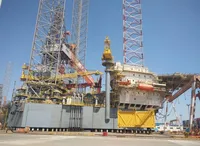 2024 Offshore RigRequest priceIn verkoophaven, ChinaKriesels Shipbroker BV
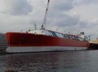 2023 New Build GastankerRequest priceIn verkoophaven, NetherlandsKriesels Shipbroker BV
 2008 TP MARINE 880 RIB OFFSHORE RIB97.500 €In verkoophaven, NetherlandsKriesels Shipbroker BV